Tutorials

Learn HVAC, one system at a time

Our goal is sharing experience and making knowledge accessible to everyone — clear, practical explanations from the field, for technicians, students and anyone curious about how these systems work.

From the fieldLessons from real service calls and maintenance work
Plain languageTechnical topics explained step by step
Free for allOpen to anyone who wants to learn
Library

All tutorials

Refrigeration

Superheat & Subcooling Explained

What these two readings tell you about refrigerant charge, and how to use them to diagnose a system.

Read tutorial →
Electrical

Testing a Run Capacitor Safely

A step-by-step check for one of the most common causes of motor and compressor failures.

Read tutorial →
Data Center

CRAH High Supply-Air Temperature

A structured way to troubleshoot a CRAH alarm — from sensor validation to the chilled-water side.

Read tutorial →
Water Treatment

Cooling Tower Water Chemistry

How pH, conductivity, cycles of concentration and LSI connect to scale, corrosion, chiller efficiency and uptime.

Read tutorial →
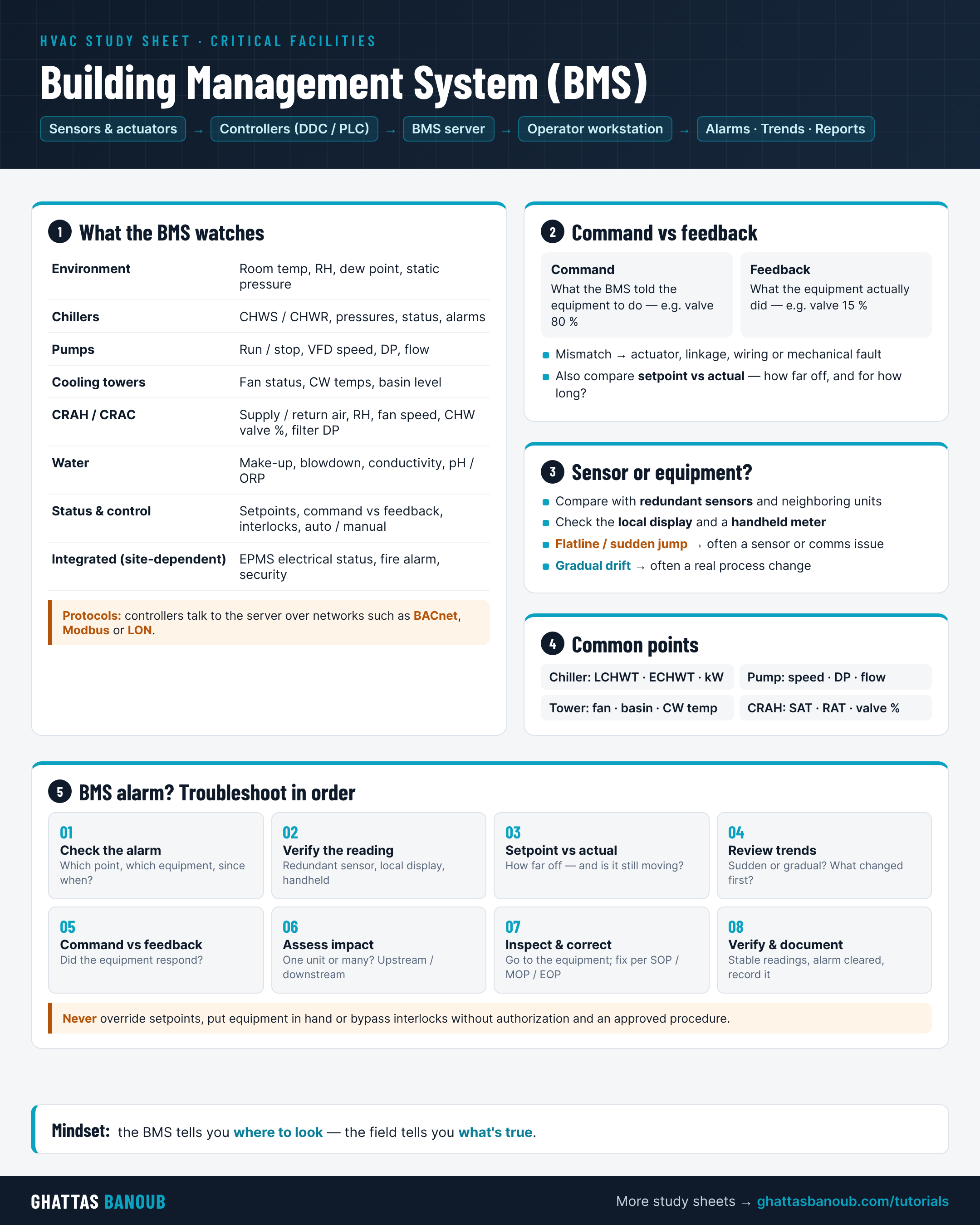
Building Management System (BMS) study sheet
Study Sheet

Building Management System (BMS)

What the BMS monitors, command vs feedback, how to tell a bad sensor from a real problem, and an 8-step alarm response.

View sheet →
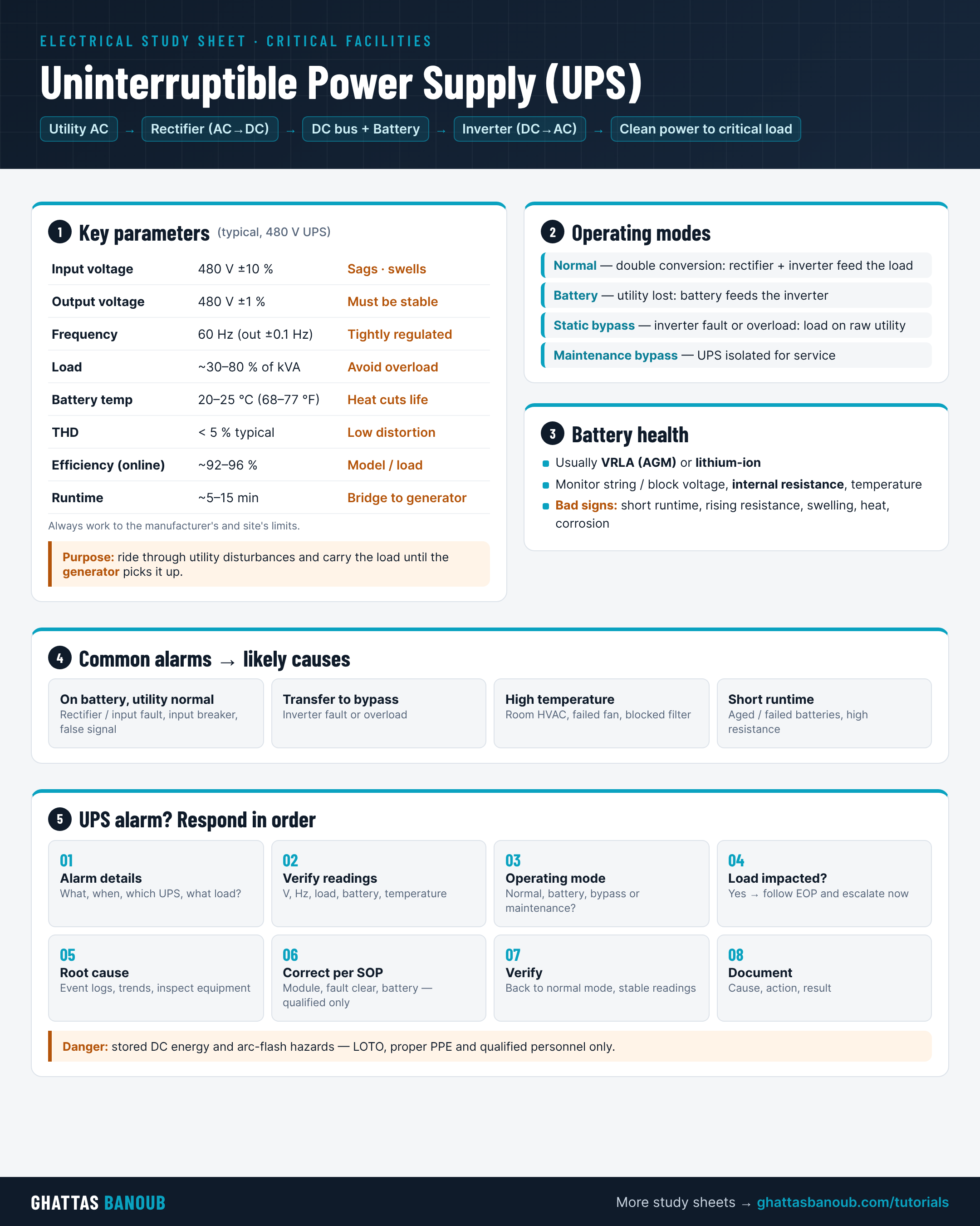
Uninterruptible Power Supply (UPS) study sheet
Study Sheet

Uninterruptible Power Supply (UPS)

Power path, operating modes, typical parameters, battery health, common alarms and an 8-step response.

View sheet →
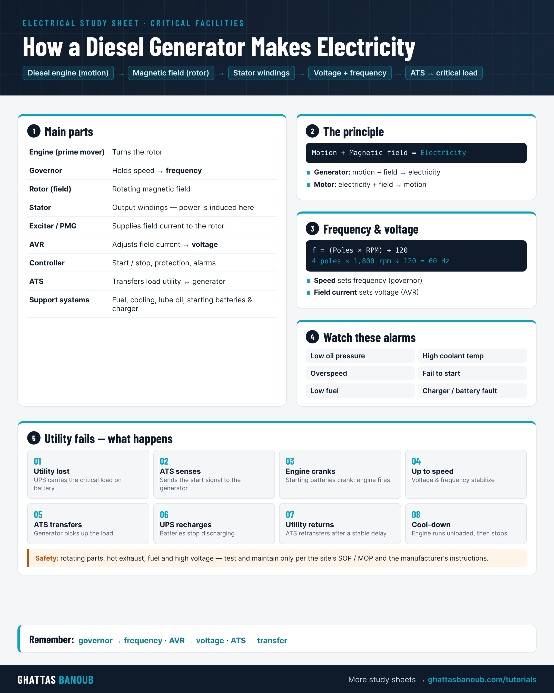
How a Diesel Generator Makes Electricity study sheet
Study Sheet

How a Diesel Generator Makes Electricity

Main parts, motion + magnetic field, the frequency formula, key alarms and what happens when utility power fails.

View sheet →
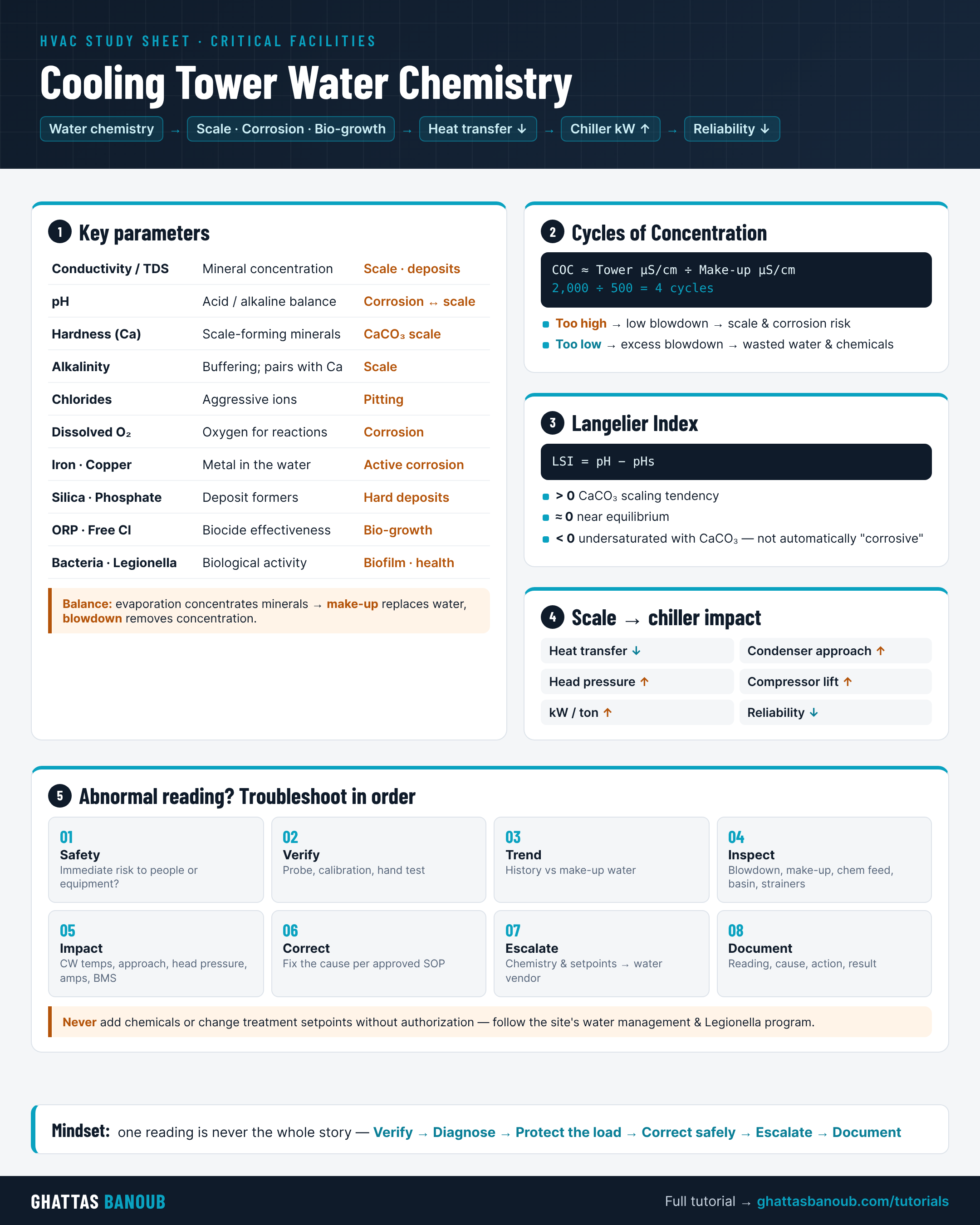
Cooling Tower Water Chemistry study sheet
Study Sheet

Cooling Tower Water Chemistry

Key parameters, cycles of concentration, LSI, scale impact on the chiller and an 8-step troubleshooting order.

View sheet →
Field Story #1 · Refrigeration

Low Charge, Hidden Leak: Finding It in the Evaporator

First leak checks came back clean — but the readings said refrigerant was missing. Persistence, nitrogen brazing and a vacuum trend test.

Read story →
Field Story #2 · Refrigeration

High Superheat + High Subcooling: Restricted TXV

Condenser OK, filter drier OK, ice right after the TXV. Why a small improvement from warming the valve wasn't good enough.

Read story →
Field Story #3 · Refrigeration

Low Superheat AND Low Subcooling: A Compressor That Can't Pump

Two readings that shouldn't appear together. Pressure ratio, amps and a pump-down test pointed to failed internal compressor valves (R-454B).

Read story →
Field Story #4 · Airflow

Frozen Evaporator from a Seized Blower Motor

Iced coil, iced suction line, iced compressor. Why I didn't run the blower or heat to defrost — and how I replaced the motor safely.

Read story →
Field Story #5 · Refrigeration

Iced Coil from a Starved Evaporator

High superheat, low subcooling and evaporator saturation 20°F below spec — all pointing to an undercharged system.

Read story →
Field Story #6 · Airflow

Normal Refrigerant Readings, Iced Coil: A Dead Blower Capacitor

Superheat, subcooling and saturation all normal — but approach and temperature split weren't. The airflow side held the answer.

Read story →
Field Story #7 · Airflow

Airflow Problem with a Healthy Blower: Closed Registers

Same symptoms as a bad blower — but the motor, amps and speed were fine. The fix was in the ductwork, not the unit.

Read story →
Field Story #8 · Refrigeration

Restriction at the Filter Drier

High superheat and subcooling, very low split, very high approach. The TXV checked out — the filter drier didn't.

Read story →
Field Story #9 · Airflow

Fouled Evaporator Coil: Reading the Heat-Transfer Clues

Normal subcooling ruled out a restriction or starved coil. Very low superheat, low split and high approach pointed to a dirty evaporator.

Read story →
Field Story #10 · Refrigeration

High Head Pressure from a Dirty Condenser

High pressures, high amps, low superheat and a 90°F/83°F air split. Poor heat rejection at the condenser — and a chemical cleaning fixed it.

Read story →
Field Story #11 · Electrical

Same Symptoms, Clean Condenser: A Dead Condenser-Fan Capacitor

Identical high-head-pressure readings — but this time the coil was clean. The condenser fan was running slow on a failed capacitor.

Read story →
Field Story #12 · Electrical

System Dead: Grounded Fan Motor, Blown Fuse and a Tripped High-Pressure Switch

Fixing the obvious faults wasn't enough. Tracing the 24V control signal led to a high-pressure safety that had also tripped.

Read story →
Field Story #13 · Electrical

Blown Fuse, Grounded Compressor

Voltage normal, fuse blown, fan motor fine — and a compressor winding to ground. A full compressor replacement done by the book.

Read story →
Field Story #14 · Refrigeration

Overfeeding: A Slow-Responding TXV

High subcooling, low superheat. Bulb and insulation were fine, but a hot-water test showed the valve reacting too slowly.

Read story →
Field Story #15 · Commercial Refrigeration

Walk-In Freezer at High Temperature

Iced evaporator, then low subcooling and high superheat. Restoring the charge — and giving a heavily loaded box time to recover.

Read story →
Field Story #16 · Commercial Refrigeration

Unfamiliar True Freezer: The Relay That Wouldn't Switch Modes

No experience with this brand's sequence. Learning the defrost steps, spotting the compressor running during defrost, and finding a failed board relay.

Read story →
Field Story #17 · Commercial Refrigeration

Unfamiliar Ice-Cream Machine: A Restricted Capillary Tube

New machine, new maker. Breaking it into inputs, outputs, control and electrical — then using nitrogen to pinpoint the restriction.

Read story →
Coming soon

More tutorials on the way

New topics are added regularly. Have a question you'd like explained? Send it in.

Library

Tutorials, field stories & study sheets

Refrigeration

Superheat & Subcooling Explained

By Ghattas Banoub · 5 min read

Pressure readings alone don't tell you much. Superheat and subcooling turn those pressures into a picture of what the refrigerant is actually doing inside the system — and that's what lets you diagnose a problem instead of guessing.

Superheat

Superheat is how much warmer the refrigerant vapor is than its boiling (saturation) temperature. It's measured on the suction line near the outdoor unit.

Superheat = Suction line temperature − Saturation temperature at suction pressure

Superheat tells you how well the evaporator is being fed. High superheat means the evaporator is starved of refrigerant; low superheat means it's overfed and liquid could reach the compressor.

Subcooling

Subcooling is how much cooler the liquid refrigerant is than its condensing (saturation) temperature. It's measured on the liquid line leaving the condenser.

Subcooling = Saturation temperature at liquid pressure − Liquid line temperature

Subcooling tells you how much liquid is stacked up in the condenser.

Which one do I charge by?

  • Fixed orifice / piston systems: charge by superheat, using the manufacturer's target superheat chart (based on indoor wet-bulb and outdoor dry-bulb temperatures).
  • TXV / EEV systems: the valve controls superheat, so charge by subcooling, using the target on the unit's nameplate or installation manual.

Reading the symptoms

Likely problemSuperheatSubcooling
Undercharge (low refrigerant)HighLow
OverchargeLow (piston) / normal (TXV)High
Restriction (metering device, filter drier)HighNormal to high
Low indoor airflow (dirty filter, coil, blower issue)LowNormal
Tip: Always check airflow first — filter, coil and blower. Adding or removing refrigerant to compensate for an airflow problem creates a second problem.
← Back to all tutorials
Electrical

Testing a Run Capacitor Safely

By Ghattas Banoub · 4 min read

A weak run capacitor is one of the most common reasons a compressor or fan motor won't start, hums, or runs hot. Testing it takes a few minutes — but it has to be done safely.

Safety first: Capacitors store energy even after power is off. Follow lockout/tagout, and always discharge the capacitor before touching the terminals.

Steps

  1. Shut off and lock out power at the disconnect, then verify zero voltage with your meter.
  2. Discharge the capacitor using an insulated resistor tool across the terminals.
  3. Photograph or label the wires before removing them, so they go back in the right place.
  4. Read the rating printed on the capacitor — the microfarad (µF) value and its tolerance (commonly ±5% or ±6%).
  5. Measure with your meter on the capacitance (µF) setting. On a dual capacitor, test C→HERM (compressor) and C→FAN separately.
  6. Compare: if the reading falls outside the tolerance range, replace it with one of the same µF rating and an equal or higher voltage rating.

Example

Rated 45 µF ±6% → acceptable range ≈ 42.3 – 47.7 µF
Measured 38.9 µF → replace
Also look for: a bulging top, leaking oil or burnt terminals. Any of these means replace — even if the reading looks fine.
← Back to all tutorials
Data Center

CRAH High Supply-Air Temperature

By Ghattas Banoub · 6 min read

In a data center, a CRAH (Computer Room Air Handler) alarm for high supply-air temperature needs a calm, structured response. The goal is to separate what you suspect from what you've confirmed — and to follow the site's procedures the whole way.

Follow your site's EOP/SOP: notify and escalate according to the facility's emergency and standard operating procedures before making changes on live critical equipment.

1. Confirm the reading

  • Compare the BMS value with the unit's local display and a handheld thermometer at the discharge.
  • Check neighboring units — is it one CRAH or the whole room?
  • Review the alarm trend: sudden jump (often a failure) or slow climb (often fouling or load).

2. Check the air side

  • Fan running? Check VFD speed, faults and belt condition (if belt-driven).
  • Filters and coil — clogged filters or a dirty coil reduce heat transfer.
  • Setpoint and control mode — has anything changed?

3. Check the chilled-water side

  • Valve position: is the chilled-water valve commanded open? Is it actually open (actuator working)?
  • Supply temperature: is chilled water arriving at the expected temperature, or is the plant running warm?
  • Delta-T and flow: a low delta-T with the valve wide open can point to low flow — check strainers, isolation valves and pumps.

4. Narrow it down

What you findPoints toward
Valve commanded 100%, little change in water temp across coilFlow problem, stuck valve or failed actuator
Valve open, chilled-water supply too warmChiller plant issue — escalate
Water side normal, low airflowFan, VFD, belt or filter problem
Local reading normal, BMS reading highSensor or wiring fault — validate and recalibrate

5. Document

Record the readings, what you checked, what you found and what you changed. Good documentation turns one incident into a lesson for the whole team.

← Back to all tutorials
Water Treatment

Cooling Tower Water Chemistry: From Readings to Reliability

By Ghattas Banoub · 8 min read

Cooling water chemistry is easy to treat as a list of numbers on a test report. In a critical facility it's much more than that — every reading is an early warning about what will happen to the condenser, the chiller and, eventually, the load it protects.

Water chemistry → Scale / Corrosion / Biological growth → Heat transfer ↓ → Condenser performance ↓ → Chiller kW ↑ → Reliability ↓

Why the water changes

A cooling tower rejects heat by evaporating water. The water leaves as vapor, but the dissolved minerals stay behind — so the remaining water gets more concentrated every hour. Two flows keep that in balance:

  • Make-up water replaces what evaporates, drifts and is drained.
  • Blowdown drains concentrated water on purpose, so fresh make-up can dilute it.

The parameters that matter

ParameterWhat it tells youMain risk
Conductivity / TDSHow concentrated the dissolved minerals areScale and deposits when high; wasted water and chemicals when low
pHAcid / alkaline balanceCorrosion when too low; scaling tendency when too high
Total & calcium hardnessScale-forming mineralsCalcium carbonate scale on condenser tubes
AlkalinityBuffering capacity; works with calcium to form scaleScale
ChloridesAggressive ionsLocalized / pitting corrosion
Dissolved oxygenOxygen available to react with metalCorrosion
Iron & copperMetal showing up in the waterEvidence that steel or copper parts are corroding
Silica & phosphateOther deposit-forming speciesHard, difficult-to-remove deposits
ORP & free chlorineHow well the oxidizing biocide is workingBiological growth when too low
Bacteria / LegionellaBiological activityBiofilm, fouling, corrosion and a health hazard

Cycles of concentration (COC)

COC tells you how many times the minerals in the make-up water have been concentrated in the tower. A quick field estimate uses conductivity:

COC ≈ Tower water conductivity ÷ Make-up water conductivity
Example: 2,000 µS/cm ÷ 500 µS/cm = 4 cycles
  • COC too high → not enough blowdown → scale, deposits and corrosion risk.
  • COC too low → too much blowdown → wasted water and treatment chemicals.

Langelier Saturation Index (LSI)

LSI = pH − pHs
  • LSI > 0 — water tends to deposit calcium carbonate scale.
  • LSI ≈ 0 — near equilibrium.
  • LSI < 0 — water is undersaturated with calcium carbonate.
Don't oversimplify: LSI only describes calcium-carbonate saturation. A negative LSI doesn't automatically mean the whole system is corrosive — and there's no single ORP number that fits every tower either. Always work to the site's own limits.

What scale does to the chiller

Scale and biofilm add thermal resistance between the refrigerant and the condenser water:

Refrigerant → Tube wall → Scale → Condenser water

The chain reaction that follows: heat transfer drops, condenser approach rises, condensing pressure climbs, compressor lift and amps increase, and kW/ton goes up. A "water problem" quietly becomes an energy problem — and, at the limit, a high-head-pressure trip.

Troubleshooting an abnormal reading

Example: condenser-water conductivity suddenly reads much higher than normal.

  1. Safety first — is there an immediate risk to people or equipment?
  2. Verify — check the probe, calibration and a hand test before trusting the number.
  3. Trend — compare with history and with make-up water conductivity.
  4. Inspect — blowdown valve and controller, make-up valve, chemical feed pumps, basin, strainers and fill.
  5. Check equipment impact — condenser water supply/return temps, condenser approach, head pressure, compressor amps and kW, BMS alarms.
  6. Correct per SOP — fix the mechanical or controls cause using the approved procedure.
  7. Escalate — chemical or setpoint changes go to the water-treatment vendor or engineer.
  8. Document — reading, trend, cause, action and final result.
Know your limits: don't add chemicals or change treatment setpoints on your own. Follow the site's water management program, biocide program and escalation path — especially where Legionella control is involved.

The mindset

One reading is never the whole story. Verify it, understand its trend, connect it to what the equipment is doing, fix the cause safely, escalate what isn't yours to change, and write it down. That's what turns water chemistry into reliability.

← Back to all tutorials
Study Sheet

Building Management System (BMS)

By Ghattas Banoub · One-page visual summary

A one-page summary of how a BMS works in a critical facility — from field devices to alarms — and how to use it to troubleshoot without jumping to conclusions.

Building Management System (BMS) study sheet
← Back to all tutorials
Study Sheet

Uninterruptible Power Supply (UPS)

By Ghattas Banoub · One-page visual summary

A one-page summary of how a double-conversion UPS keeps the critical load online, what to watch, and how to respond to an alarm safely.

Uninterruptible Power Supply (UPS) study sheet
← Back to all tutorials
Study Sheet

How a Diesel Generator Makes Electricity

By Ghattas Banoub · One-page visual summary

A one-page summary of how a standby diesel generator produces power, what controls voltage and frequency, and the sequence from utility loss to transfer.

How a Diesel Generator Makes Electricity study sheet
← Back to all tutorials
Study Sheet

Cooling Tower Water Chemistry

By Ghattas Banoub · One-page visual summary

A one-page companion to the Cooling Tower Water Chemistry tutorial.

Cooling Tower Water Chemistry study sheet
← Back to all tutorials
Field Story #1 · Refrigeration

Low Charge, Hidden Leak: Finding It in the Evaporator

By Ghattas Banoub · From the field

Call: No AC. The system was not cooling properly.

Readings

I inspected the full refrigeration cycle — pressures, saturation points and temperatures. The refrigerant level was below the normal range.

Diagnosis

Low charge means a leak somewhere. I searched with an electronic leak detector, and at first everything looked tight. I kept searching until I found the leak in the evaporator.

Repair

  1. Recovered the refrigerant — moisture could have entered through the leak, so I didn't reuse it.
  2. Removed the cores and brazed the leak with about 5 psig nitrogen flowing.
  3. Replaced the filter drier — standard practice on any opened system.
  4. Pressure-tested the braze with nitrogen at 150 psig — no leak.
  5. Evacuated to 300 microns and watched the trend for 15 minutes — passed.
  6. Opened the service valves and charged with new refrigerant to the manufacturer's subcooling spec.

Verification

Double-checked for leaks — none. System running normally.

Takeaway: a clean first leak check doesn't mean there's no leak. If the readings still say refrigerant is missing, keep looking.
← Back to all tutorials
Field Story #2 · Refrigeration

High Superheat + High Subcooling: Restricted TXV

By Ghattas Banoub · From the field

Call: No AC. The system was running but not cooling properly.

Readings

Both subcooling and superheat were high — a restriction pattern.

Ruling things out

  • Condenser coil: checked — passed.
  • Filter drier: same temperature before and after — no restriction there.
  • TXV: more than 2°F drop across it and ice directly after the valve.

Testing the TXV

I warmed the valve with a hair dryer and ran heating mode to clear any possible ice inside. Superheat and subcooling dropped a little — the TXV was responsible — but the improvement was limited.

Repair

  1. Recovered the refrigerant (possible moisture in the circuit).
  2. Replaced the TXV and the filter drier.
  3. Evacuated and tested.
  4. Opened the valves and charged with new refrigerant to spec.

Verification

System cooling properly.

Takeaway: a temporary improvement tells you where the problem is — it doesn't fix it.
← Back to all tutorials
Field Story #3 · Refrigeration

Low Superheat AND Low Subcooling: A Compressor That Can't Pump

By Ghattas Banoub · From the field

Call: No AC. The system was not cooling properly.

Readings that didn't fit

Superheat and subcooling were both low — a combination that normally doesn't appear together:

  • High SH + high SC usually means a restriction.
  • Low SH + high SC usually means a TXV stuck open, overfeeding liquid back to the compressor.

So I inspected every component to isolate the problem. The pressure ratio was below spec and compressor current was below spec — the compressor wasn't pumping.

Confirming it

I ran a pump-down test with the compressor running — it failed. And when the compressor shut off, low and high pressures equalized quickly. That points to internal valve failure.

Repair

  1. Recovered the refrigerant, then purged with nitrogen to push out any remaining A2L refrigerant before brazing.
  2. Replaced the compressor, brazing with about 5 psig nitrogen flowing.
  3. Pressure-tested the brazes at 200 psig nitrogen — passed.
  4. Evacuated to 300 microns; the trend stayed stable for 15 minutes after the pump was off.
  5. Charged R-454B as liquid per spec, then waited 20 minutes for it to stabilize, per the manufacturer.

Verification

System working properly. I documented all trends before and after the repair.

Takeaway: when readings contradict the usual patterns, test the compressor itself — ratio, amps and a pump-down test tell the story.
← Back to all tutorials
Field Story #4 · Airflow

Frozen Evaporator from a Seized Blower Motor

By Ghattas Banoub · From the field

Call: No AC. The system was running but not cooling.

What I found

The suction pipe and the compressor were iced. I shut the system off, removed the furnace and coil covers, and found the evaporator completely iced. The blower motor's bearings were bad and the motor was seized.

Repair

  1. Turned power off at the circuit breaker and the furnace disconnect.
  2. Discharged the capacitor before removing the old motor wiring.
  3. Replaced the blower motor.
  4. Restored power and ran the blower only briefly to test the new motor, then shut power off again.
Why not defrost with the blower or heat? With the coil iced, the airflow path is blocked — running the blower risks overcurrent, and running a gas furnace risks overheating.

Defrosting

I removed the ice with a hot-water manual pump and waited until the coil, suction piping and every affected area were fully defrosted before returning to cooling mode.

Verification

Electrical readings, refrigeration readings, airflow and temperatures — all passed.

← Back to all tutorials
Field Story #5 · Refrigeration

Iced Coil from a Starved Evaporator

By Ghattas Banoub · From the field

Call: No AC. The system was running but not cooling.

First, safe defrost

Ice on the suction pipe and evaporator coil. I disconnected power at the circuit breaker and disconnect and removed the ice with a hot-water manual pump.

Readings

  • Superheat: high
  • Subcooling: low
  • Evaporator approach: high
  • Supply / return temperature difference: outside spec
  • Evaporator saturation: about 20°F below spec

Diagnosis

Every symptom pointed to an evaporator starved of refrigerant.

Repair

Added refrigerant until subcooling and temperature split met the manufacturer's spec.

← Back to all tutorials
Field Story #6 · Airflow

Normal Refrigerant Readings, Iced Coil: A Dead Blower Capacitor

By Ghattas Banoub · From the field

Call: No AC. The system was running but not cooling.

First, safe defrost

Ice on the suction pipe and evaporator coil. Power off at the breaker and disconnect, then a hot-water manual pump to remove the ice.

Readings

  • Superheat and subcooling: normal
  • Evaporator saturation: normal
  • Evaporator approach: high
  • Supply / return temperature difference: more than spec

Diagnosis

With the refrigerant side normal, the symptoms pointed to airflow. I checked the blower's electrical and found the run capacitor dead.

Repair & verification

Replaced the capacitor and test-commissioned the system — every reading back within spec.

← Back to all tutorials
Field Story #7 · Airflow

Airflow Problem with a Healthy Blower: Closed Registers

By Ghattas Banoub · From the field

Call: No AC. The system was running but not cooling.

First, safe defrost

Ice on the suction pipe and evaporator coil. Power off at the breaker and disconnect, then removed the ice with a hot-water manual pump.

Readings

  • Superheat and subcooling: normal
  • Evaporator saturation: normal
  • Evaporator approach: high
  • Supply / return temperature difference: more than spec

Diagnosis

The symptoms pointed to airflow. But the blower's electrical readings were normal and its speed was normal. So I followed the air: I inspected the ductwork and every supply and return diffuser — and found the basement supply registers and the returns closed, choking the airflow.

Repair & verification

Opened them and tested — system working properly.

Takeaway: an airflow problem isn't always in the air handler. Check the whole air path.
← Back to all tutorials
Field Story #8 · Refrigeration

Restriction at the Filter Drier

By Ghattas Banoub · From the field

Call: No AC. The system was running but not cooling.

Readings

  • Superheat and subcooling: high
  • Temperature split: very low
  • Evaporator approach: very high

All indicators of a restriction.

Isolating it

  • Across the TXV: temperature drop normal.
  • Across the filter drier: more than 2°F difference — the restriction.

Repair

  1. Recovered the refrigerant and replaced the filter drier, brazing with 5–10 psig nitrogen flowing.
  2. Pressure-tested the brazes at 150 psig nitrogen — passed.
  3. Evacuated to 300 microns; with the pump off, the vacuum rose slowly to about 400 microns over 15 minutes.
  4. Charged refrigerant to the manufacturer's spec.

Verification

Test commissioning successful.

← Back to all tutorials
Field Story #9 · Airflow

Fouled Evaporator Coil: Reading the Heat-Transfer Clues

By Ghattas Banoub · From the field

Call: No AC. The system was running but not cooling.

Readings

  • Subcooling: normal — so no restriction and no starved evaporator
  • Superheat: very low
  • Temperature split: very low
  • Evaporator approach: very high

Diagnosis

The pattern pointed to poor heat transfer at the evaporator — a fouled coil. I inspected it and found it very dirty.

Repair

  1. Shut the system down at the breaker and disconnect, and locked the disconnect.
  2. Cleaned the evaporator coil with chemical cleaner.
  3. Restored power and ran cooling mode.

Verification

All measurements in normal range.

← Back to all tutorials
Field Story #10 · Refrigeration

High Head Pressure from a Dirty Condenser

By Ghattas Banoub · From the field

Call: No AC. The system was running but not cooling.

Readings

MeasurementResult
High pressureAbove spec
Low pressureAbove spec
SuperheatBelow normal
SubcoolingAbove spec
Return / supply air90°F / 83°F
Vapor & liquid saturation tempsHigh
Suction & discharge line tempsHigh
Compressor ampsAbove spec

Diagnosis

Everything pointed to a heat-transfer problem at the condenser: high head pressure, vapor not fully condensing, which pushed evaporator pressure and saturation up too.

Repair & verification

Cleaned the condenser coil with chemical cleaner, restored power and test-commissioned — all measurements in normal range.

← Back to all tutorials
Field Story #11 · Electrical

Same Symptoms, Clean Condenser: A Dead Condenser-Fan Capacitor

By Ghattas Banoub · From the field

Call: No AC. The system was running but not cooling.

Readings

The same pattern as a dirty condenser: high and low pressures above spec, superheat below normal, subcooling above spec, 90°F return / 83°F supply, high saturation and line temperatures, and compressor amps above spec.

Diagnosis

Poor heat rejection at the condenser — but the coil was clean. That left the condenser fan. Its electrical readings showed a dead run capacitor, so the fan was running at low speed and drawing more current.

Repair

Discharged the stored energy from the capacitor before touching it, then replaced it.

Verification

Restored power and test-commissioned — all measurements in normal range.

Takeaway: identical readings can have different causes. Rule out the obvious one, then keep going.
← Back to all tutorials
Field Story #12 · Electrical

System Dead: Grounded Fan Motor, Blown Fuse and a Tripped High-Pressure Switch

By Ghattas Banoub · From the field

Call: No AC. The system was not running.

Electrical checks

  • Supply voltage: normal
  • Fuse: blown
  • Compressor windings: resistance normal
  • Condenser fan motor windings: grounded
  • Condenser fan run capacitor: dead

Repair — round one

Replaced the condenser fan motor, its capacitor and the fuse, then called for cooling. The system still didn't run.

Tracing the control circuit

The control signal was arriving at the outdoor unit, but 24V wasn't reaching the contactor. Tracing the circuit, I found the high-pressure switch had tripped. I reset it and the system started.

Verification

High and low pressure, superheat, subcooling, temperature split, saturation temps, line temps, compressor amps and condenser fan amps — all normal. System working fine.

Takeaway: one failure can trip a safety downstream. After the repair, follow the control signal all the way to the load.
← Back to all tutorials
Field Story #13 · Electrical

Blown Fuse, Grounded Compressor

By Ghattas Banoub · From the field

Call: No AC. The system was not running.

Electrical checks

  • Supply voltage: normal
  • Fuse: blown
  • Compressor windings: grounded
  • Condenser fan motor windings: fine
  • Fan capacitor: good

That isolated the problem to a failed compressor.

Repair

  1. Recovered the refrigerant.
  2. Installed the new compressor, brazing with 5–10 psig nitrogen flowing, and replaced the heavy-duty capacitor and fuses.
  3. Pressure-tested with nitrogen at 150 psig for 10 minutes — no change.
  4. Evacuated to 300 microns.
  5. Charged refrigerant to spec.

Verification

Cooling mode on — electrical and refrigeration readings all in normal range.

← Back to all tutorials
Field Story #14 · Refrigeration

Overfeeding: A Slow-Responding TXV

By Ghattas Banoub · From the field

Call: No AC. The system was running.

Readings

Electrical readings normal. On the refrigeration side, subcooling high and superheat low — a TXV pattern.

Isolating it

  • Removed the evaporator cover — the TXV bulb and its insulation were in place and correct.
  • Tested the TXV with hot water — it responded slowly to changes in superheat and subcooling.

Repair

  1. Recovered the refrigerant and replaced the TXV, brazing with 5–10 psig nitrogen to prevent oxidation.
  2. Pressure-tested at 150 psig nitrogen.
  3. Evacuated to 300 microns and watched the trend for 15 minutes with the pump off — only a slow rise.
  4. Charged to spec.

Verification

Test commissioning successful.

← Back to all tutorials
Field Story #15 · Commercial Refrigeration

Walk-In Freezer at High Temperature

By Ghattas Banoub · From the field

Call: High temperature in a walk-in freezer.

What I found

The evaporator was iced. I used the defrost timer to run a defrost cycle and clear the ice, then returned the system to cooling.

Readings

Subcooling low, superheat high — low refrigerant.

Repair

Added refrigerant until subcooling reached normal. Superheat came down, but stayed above normal because the thermal load in the box was still high.

Verification

I waited one hour and tested again — the system was working fine.

Takeaway: right after a warm-up, a high box load affects superheat. Give the system time and re-check before adjusting further.
← Back to all tutorials
Field Story #16 · Commercial Refrigeration

Unfamiliar True Freezer: The Relay That Wouldn't Switch Modes

By Ghattas Banoub · From the field

Call: High temperature on a True freezer — a brand whose sequence of operation I hadn't worked with before.

What I found

The evaporator was iced.

Learning the system

I used AI (ChatGPT) to find the steps for starting defrost on this make and model, and started a defrost.

The clue

During defrost, the compressor kept running with the heaters on — so the ice wasn't clearing. I followed the control circuit to the relay on the board that switches between cooling and defrost. It had failed.

Repair & verification

Replaced the relay, removed the ice with hot water and tested — system working fine.

Takeaway: not knowing a system isn't the problem. Learn its sequence, then watch what it actually does.
← Back to all tutorials
Field Story #17 · Commercial Refrigeration

Unfamiliar Ice-Cream Machine: A Restricted Capillary Tube

By Ghattas Banoub · From the field

Call: An ice-cream machine not working — no cooling. I had no experience with this machine or maker.

Learning the system

I used AI to understand the sequence of operation, then divided the system into inputs, outputs, control and electrical and followed it step by step.

Readings

  • Compressor: very hot
  • Superheat: very high
  • Evaporator, condenser coil and condenser fan: fine
  • Across the filter drier and the solenoid valve: normal — no significant temperature difference

Diagnosis

I suspected the capillary tube. I recovered the refrigerant and used nitrogen to confirm which part was restricted — it was the capillary.

Repair & verification

Replaced the capillary tube, completed the full open-system procedure, and tested — running fine.

← Back to all tutorials
Stay updated

Get new tutorials by email

Subscribe and be the first to know when a new tutorial is published. No spam — unsubscribe any time. Privacy Policy

Ask a question

Want a topic explained?

Send your question or suggest a topic for the next tutorial.

ghattasbanoub@gmail.com